A full product cycle: schematic and PCB layout in KiCad, fabrication, then hand assembly — at which point the board didn’t work. I traced the fault to one mis-routed MOSFET pin in my own layout, worked around it and wrote it up, modeled the enclosure in Onshape off my board’s hole pattern, printed it, and measured the finished device against its control inputs on a scope.
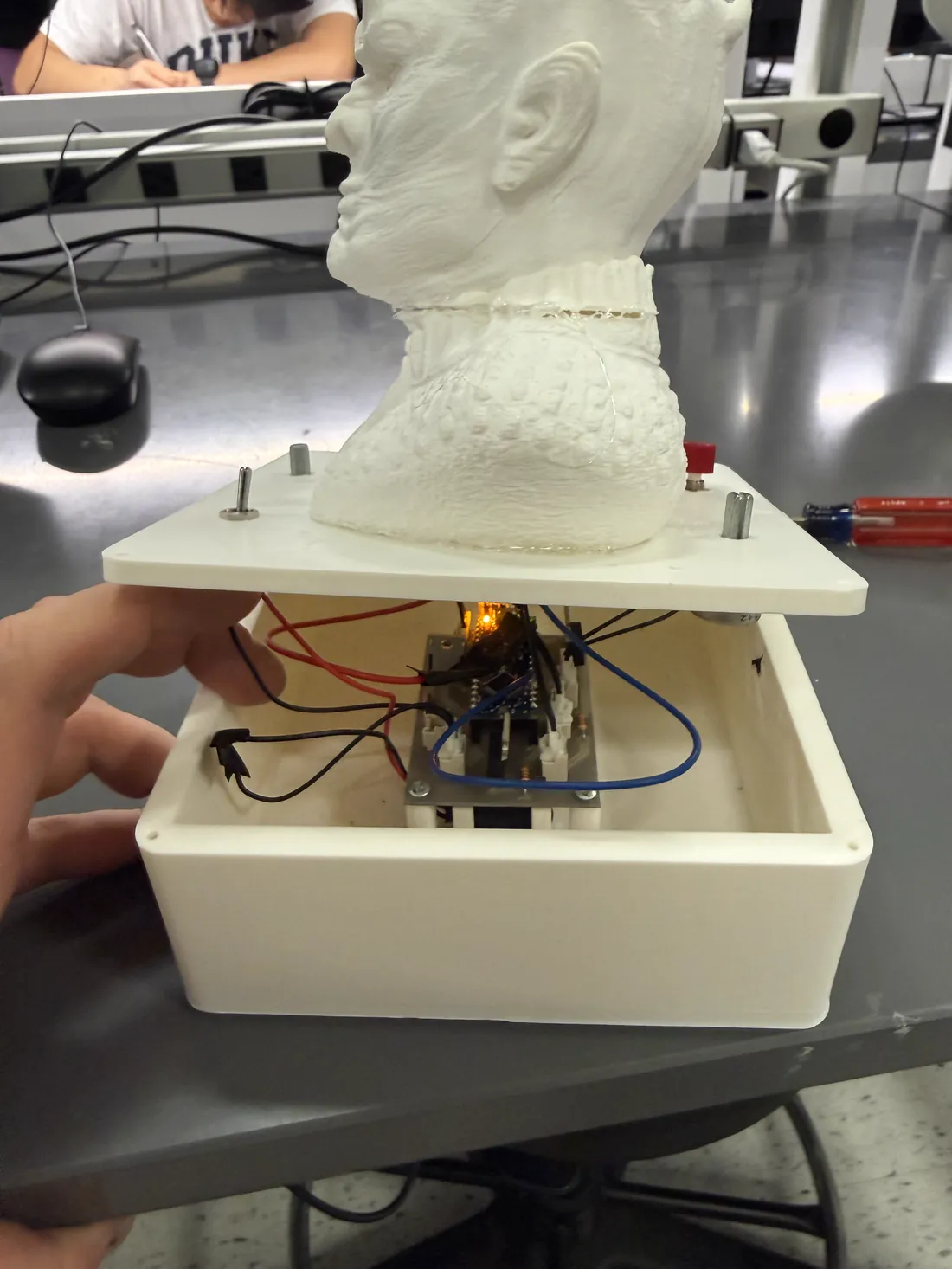
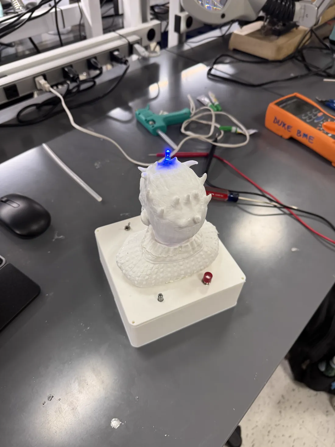
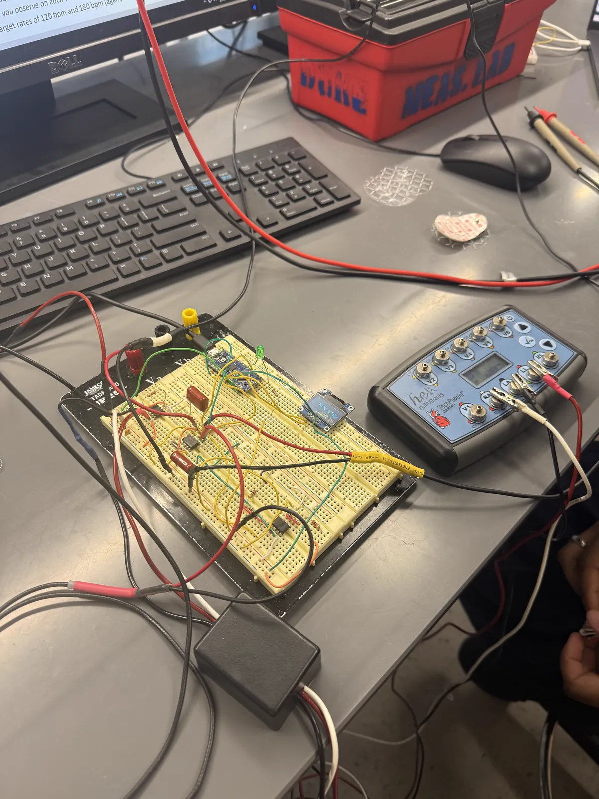
The board running before it went into the enclosure. No sound.Board seated on the M3 pillars, lid lifted.Finished unit, LED lit.
Board, firmware and root cause
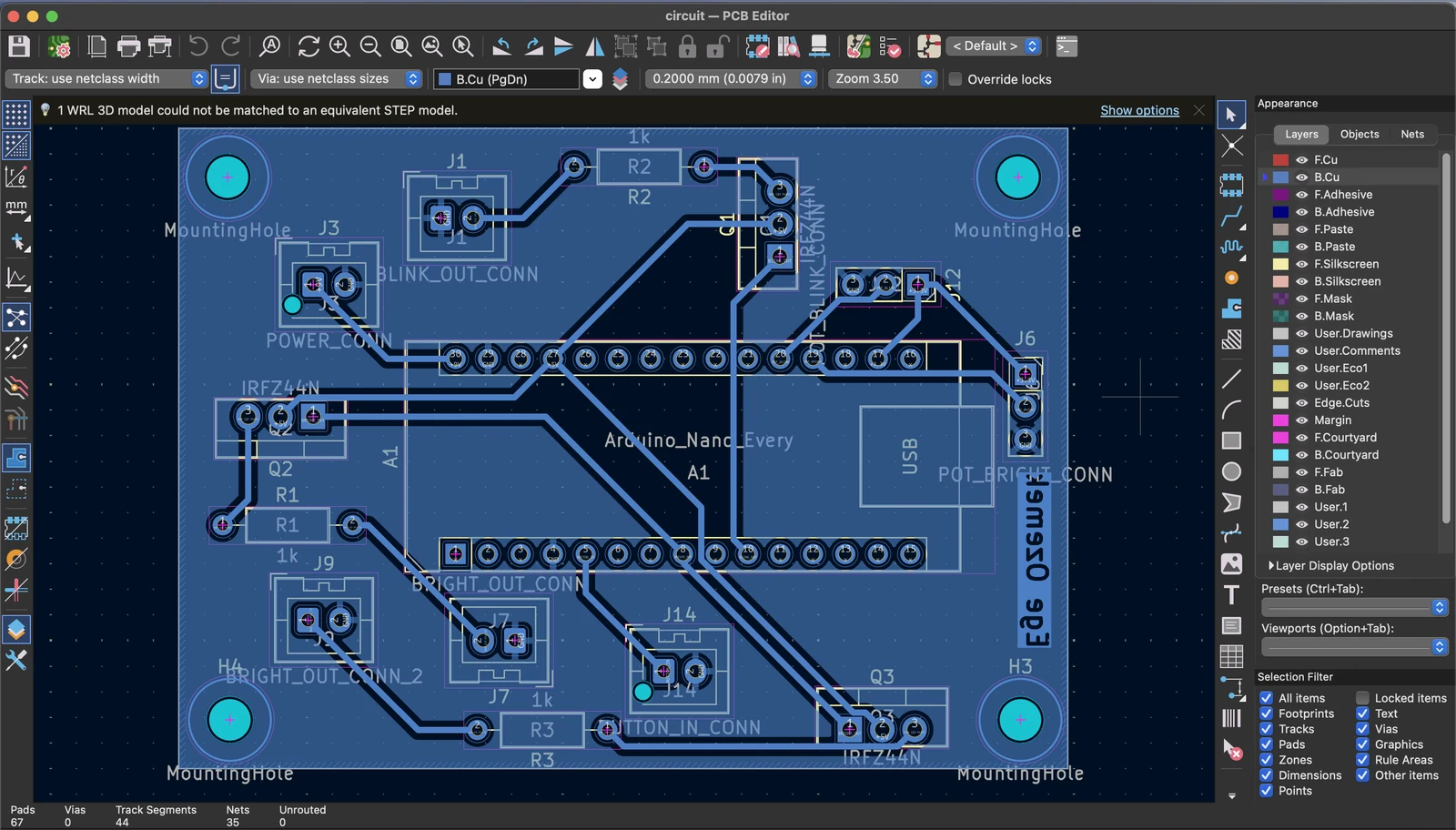
Schematic capture and layout in KiCad, fabricated and hand-assembled — then debugged when it came back and wouldn’t switch.
Arduino Nano Every, three IRFZ44N low-side MOSFET switches, two 10 kΩ potentiometers, a push button, 9 V supply.
Four M3 mounting holes (3.2 mm) on a 61.8 × 42.4 mm pattern — the datum the enclosure was later built from.
Root cause: the assembled board would not switch the blink LED. I traced it to Q1 (IRFZ44N) with its source routed to +5 V instead of ground — V_GS could never swing positive, so the MOSFET never turned on.
Workaround: bypassed Q1 and drove the LED directly from D10 through a 330 Ω series resistor. Both the fault and the fix are written up in the technical report.
Firmware on the Nano Every (megaAVR): a state machine with a hardware-interrupt button and millis() timing — PWM brightness on D5, blink toggle on D10, heartbeat on D13.
Enclosure and bench validation
An enclosure modeled around the board I had just laid out, printed, then measured against its control inputs.
Designed the base from scratch in Onshape, dimensioned straight off the KiCad board: four M3-tapped pillars on the 61.8 × 42.4 mm hole pattern, four corner posts forming a 48.5 × 26.5 × 17.5 mm cradle for the 9 V cell, a 15 × 15 mm wire channel in the lid, and countersunk M3 corner screws.
Repaired a sourced mesh in Blender (non-manifold edges, loose parts), converted 3MF → STL, hollowed it, and cut channels for three blue LEDs.
Printed on 3DPrinterOS at 0.15 mm layers with organic supports and a brim — roughly a 20-hour print.
Characterized on a scope: brightness duty cycle tracks its control voltage at R² = 0.99994, blink rate at R² = 0.974, and the heartbeat period held 1000 ms across all ten trials.
Working on a layperson-operable handheld tympanometer for pediatric middle-ear screening in underserved communities — funded by PCORI and Duke Global Health, with clinical and industry partners. My part: adding an on-device display, standing up the tympanogram-labeling web stack, and building the labeling pipeline for its planned on-device ML classifier.
The display state machine running on the device. No sound.
Firmware and display
Added an OLED display subsystem to a BLE medical device on Zephyr RTOS / nRF52833.
Designed a 10-state display state machine that mirrors the measurement flow.
Ran a display-hardware tradeoff study (mono OLED vs Memory LCD vs e-paper vs TFT) against power, BOM cost, and measurement-noise constraints.
Ported the display driver from I²C to SPI.
Diagnosed a blank-screen failure down to a pin conflict with the debugger's internal UART and resolved it on validated hardware.
Full-stack and infrastructure
Stood up a Flask web app for audiologists to label ~5,000 tympanograms — the ground-truth dataset for the device’s planned on-device ML classifier.
Python · Jinja · HTMX · SQLite with server-side matplotlib rendering, running on a Linux VM.
Built the labeling pipeline that will feed a planned on-device ML classifier — the classifier is in development; my role is the data pipeline, not training the model.