Mechanical & CAD

Hybrid III 6YO Neck — CAD & Engineering Drawings

The neck assembly of a Hybrid III 6-year-old crash-test dummy, modeled in Onshape and then detailed to drafting standard: an assembly sheet with a bill of materials, plus a dimensioned sheet for every part.

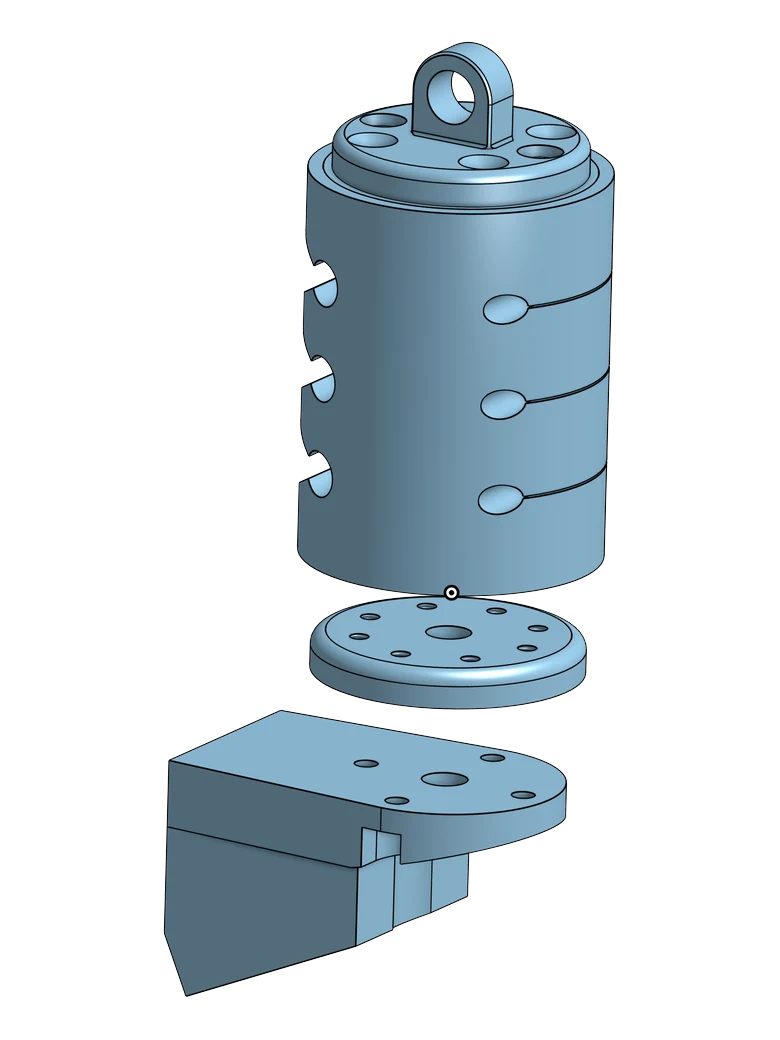
Exploded 3D view of the neck assembly: the molded neck column with three scalloped notches down its side sits above a circular bottom plate, which sits above the wedge-shaped lower neck bracket.
The assembly exploded.
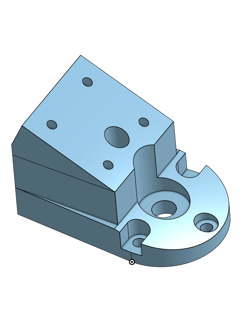
3D view of the Lower Neck Bracket: a wedge-shaped aluminum block with a rounded flange, a large central bore and several threaded holes.
Lower Neck Bracket.
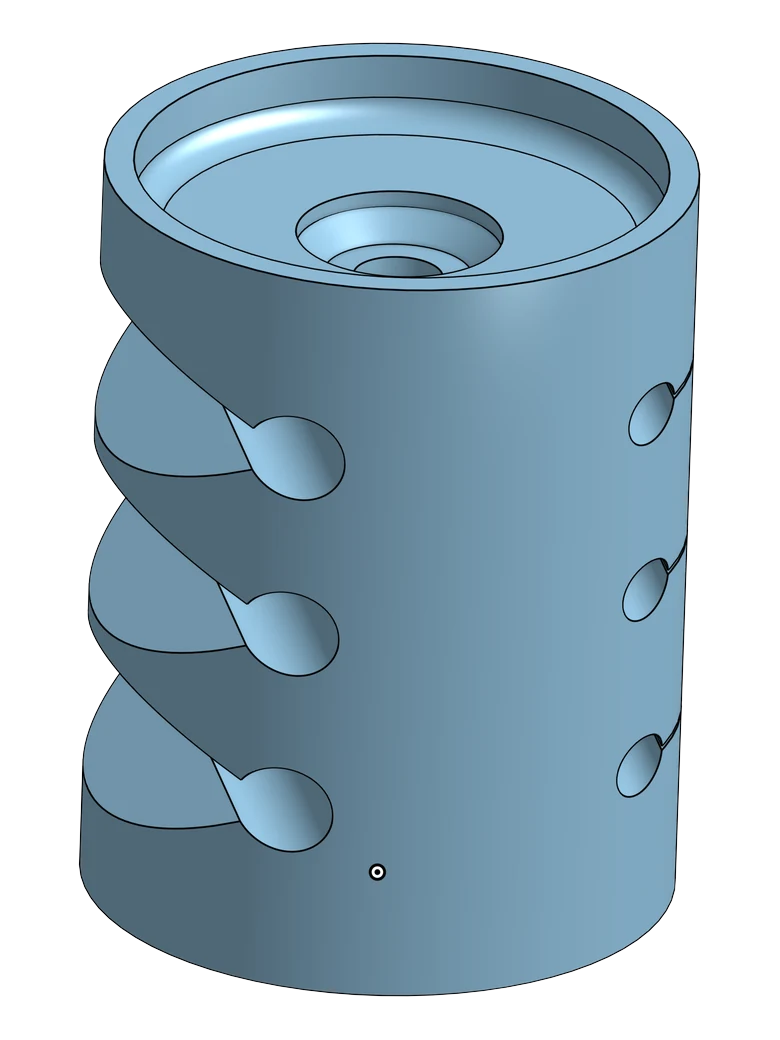
3D view of the Molded Neck: a butyl cylinder with three scalloped notches cut down one side and a recessed, stepped bore in the top face.
Molded Neck.
  • Five-part assembly, materials called out on the BOM: Molded Neck (butyl), Top, Nodding and Bottom Plates (steel), Lower Neck Bracket (aluminum).
  • Third-angle projection throughout, with a standard tolerance block (.XX / .XXX / .XXXX), a zoned border, and the usual sheet notes — DO NOT SCALE DRAWING, BREAK ALL SHARP EDGES AND REMOVE BURRS.
  • Feature callouts: counterbores (⌴ Ø.813 ▼1.730), 82° countersinks (⌵ Ø.411 × 82°), three thread specs (#10-32, #10-24, ¼-20), chamfers (.120 × 45°), radii, and angular dimensions.
  • Six detail sheets behind the assembly: the five BOM parts plus the load cell.
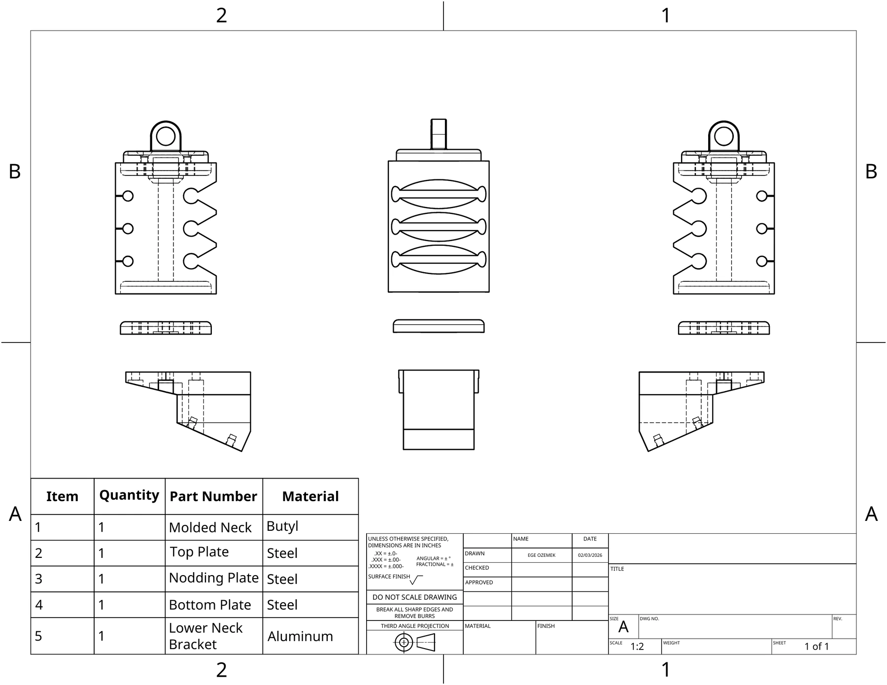
Assembly drawing of the Hybrid III 6YO neck: front, side and rear views of the stacked assembly, above a bill of materials listing five items — Molded Neck in butyl, Top Plate, Nodding Plate and Bottom Plate in steel, and the Lower Neck Bracket in aluminum.
Assembly sheet — five items, quantities and materials on the BOM.
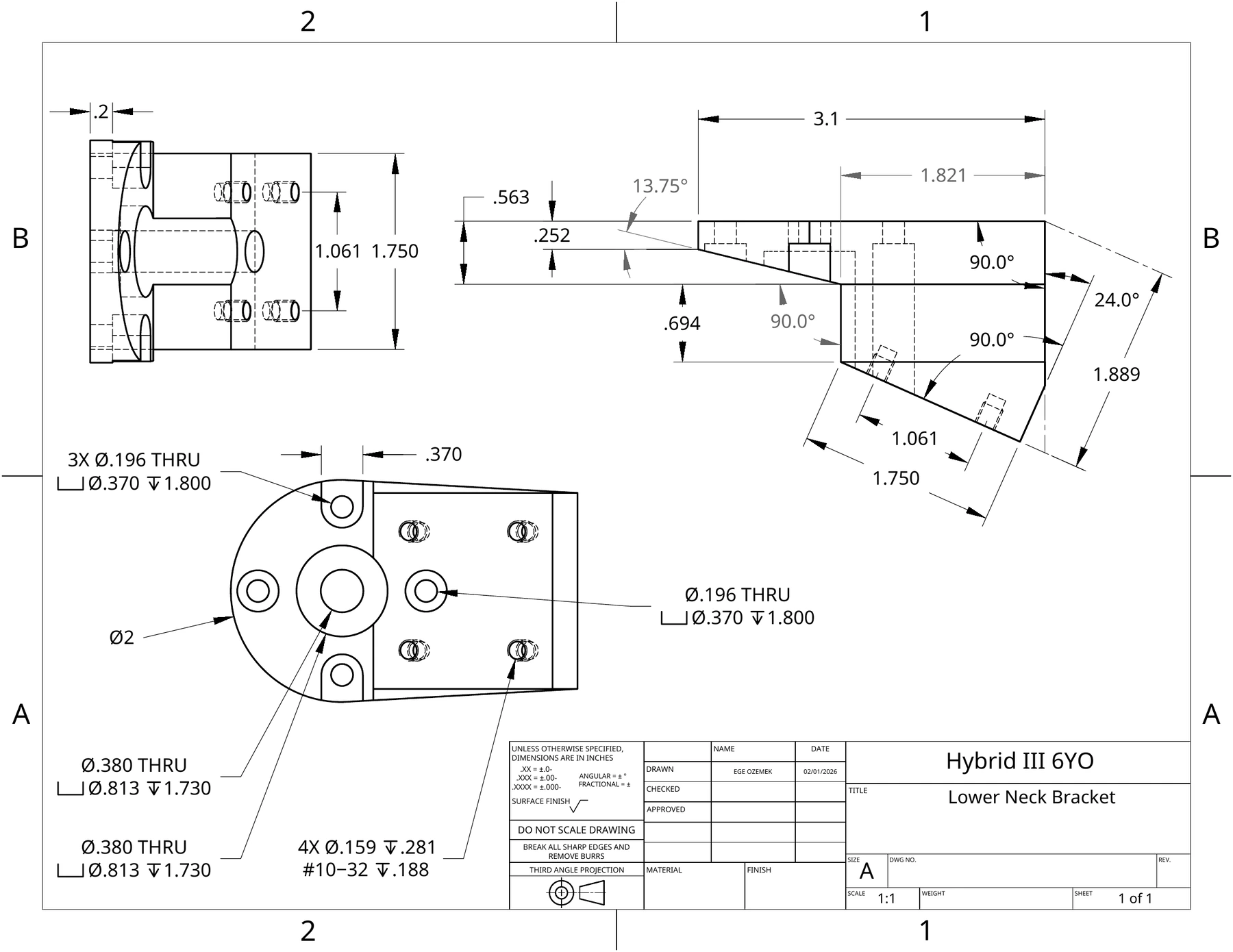
Engineering drawing of the Lower Neck Bracket: a front view, a side view with 13.75° and 24° angular dimensions, and a bottom view calling out three Ø.196 through holes with Ø.370 counterbores, two Ø.380 through holes with Ø.813 counterbores, and four #10-32 threaded holes.
Lower Neck Bracket — the most feature-dense sheet in the set.
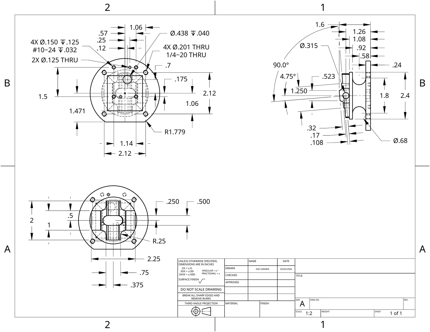
Engineering drawing of the load cell part: three views calling out four Ø.150 holes tapped #10-24 deep .032, four Ø.201 holes tapped ¼-20 through, two Ø.125 through holes, a Ø.438 counterbore deep .040, an R1.779 outer radius and a 4.75° angular dimension.
Load cell — three thread specs on one part: #10-24, ¼-20 and plain clearance.
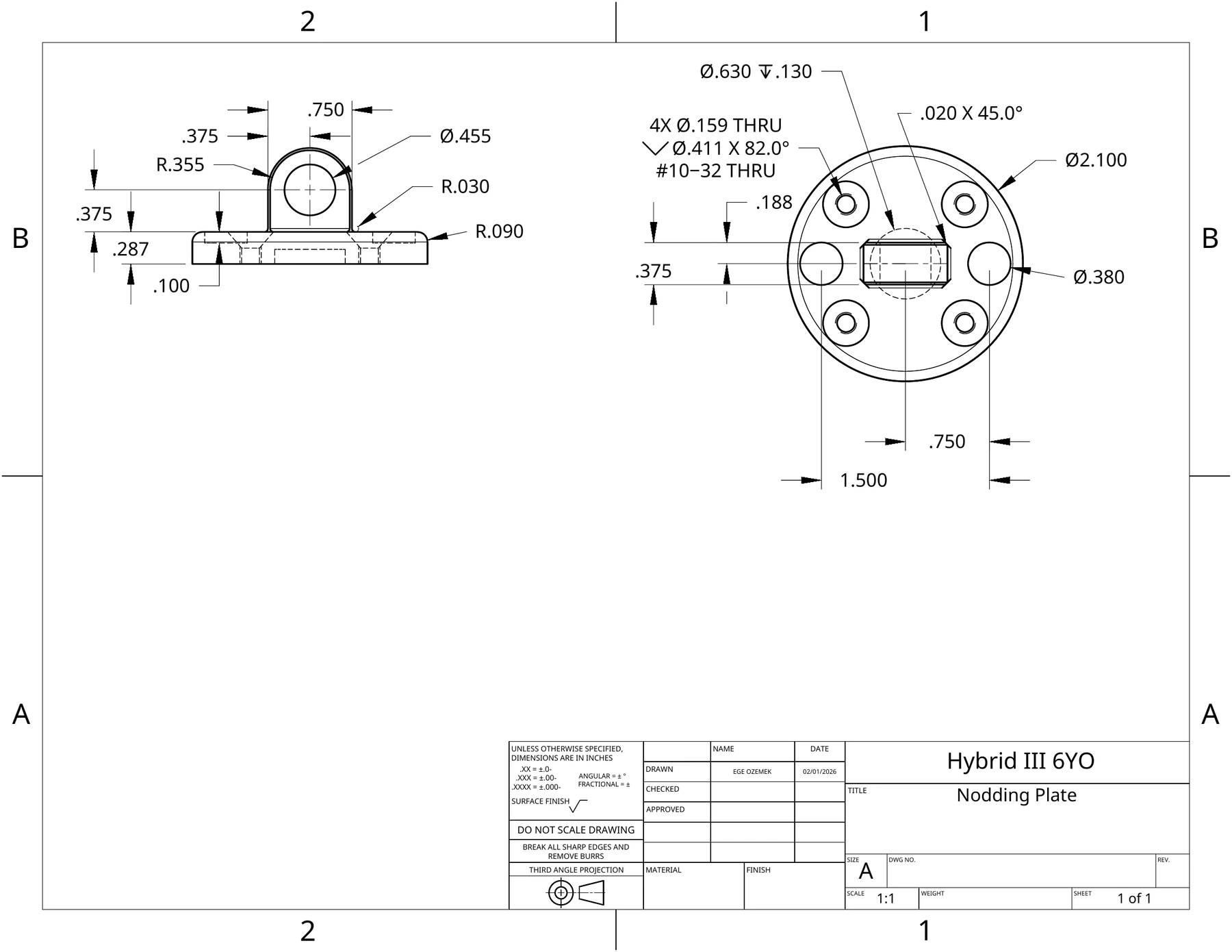
Engineering drawing of the Nodding Plate: a side view of the raised clevis with R.355 and R.090 radii, and a plan view calling out four Ø.159 holes countersunk Ø.411 at 82° and tapped #10-32 through, a Ø.630 counterbore deep .130, and a .020 × 45° chamfer on a Ø2.100 plate.
Nodding Plate — 82° countersinks, tapped #10-32 through.

ToolsOnshape · Engineering drawings · Design for manufacture

Enclosure Design & 3D Printing

The lightbox enclosure, modeled in Onshape around the board I had just laid out. Mounting pattern, battery cradle and wire routing all came off the PCB dimensions, then it was printed and assembled with the board inside.

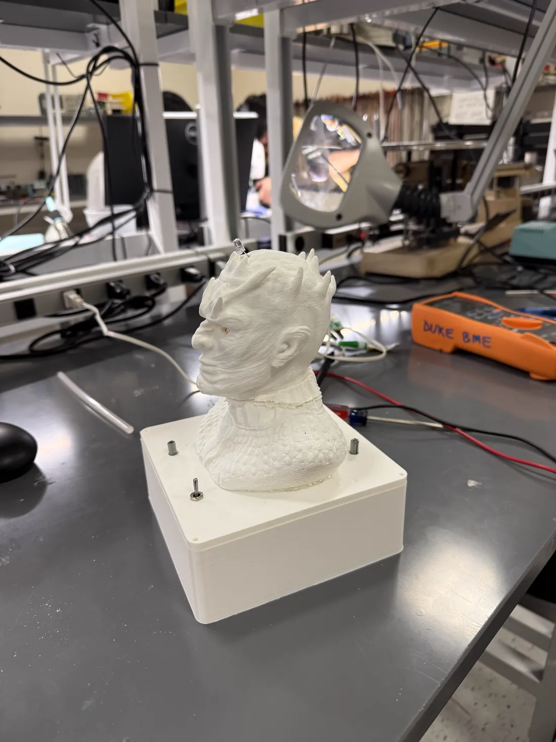
The printed enclosure in profile on a lab bench: a white 3D-printed base with visible layer lines, M3 posts standing at the corners, and the printed figure mounted on the lid.
Printed base and lid, M3 corner posts standing proud.
  • Four M3-tapped pillars placed on the PCB’s own 61.8 × 42.4 mm hole pattern, so the board drops straight in.
  • Four corner posts forming a 48.5 × 26.5 × 17.5 mm cradle for the 9 V cell, a 15 × 15 mm wire channel in the lid, and countersunk M3 corner screws.
  • Sourced mesh repaired in Blender — non-manifold edges and loose parts — then converted 3MF → STL, hollowed, and channeled for three LEDs.
  • Printed on 3DPrinterOS: 0.15 mm layers for surface detail, organic supports, brim; about a 20-hour print.

ToolsOnshape · Blender · FDM 3D printing · Design for assembly